
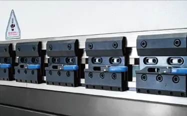
Options & automation
Build around your workpiece.
These are auxiliary options and application-specific equipment, separate from the catalogue standard assemblies. Select positioning, measurement, clamping and handling equipment around the part and machine.
Optional equipment
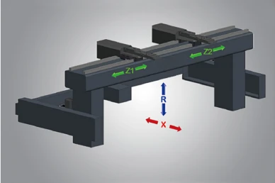
Multi-axis backgauge packages
Additional independently positioned fingers and axes support more involved workpiece positioning. These are backgauge-axis counts, not a count of all machine axes.
- 4 axes: X, R, Z1, Z2
- 5 axes: X, R, Z1, Z2, X1
- 6 axes: X1, X2, R1, R2, Z1, Z2
Optional equipment
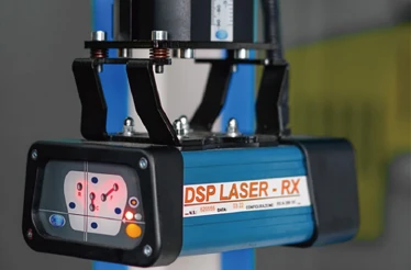
Laser safety protection
The catalogue illustrates a DSP laser protection device at the tooling area. The machine's complete safeguarding arrangement must be specified for the equipment and destination requirements.
- DSP laser device pictured in the catalogue
- Safety integration is confirmed as part of the machine package
Optional equipment
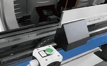
Laser angle measurement
Laser angle measurement provides information about the workpiece bend angle. It is a process-measurement option and serves a different purpose from the laser safety device.
- Workpiece angle measurement during bending
- Controller and machine integration require confirmation
Optional equipment
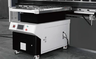
CNC follower supports
Unlike manually positioned front supports, a follower support tracks the workpiece as it turns during a bend. The CNC system calculates and controls the following angle and speed.
- CNC-controlled following motion
- Lateral positioning along the support guide
Optional equipment
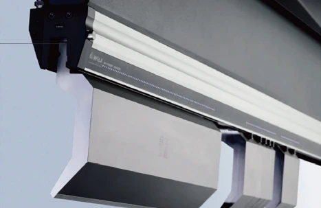
WILA hydraulic upper clamping
The WILA upper-tool system uses hydraulic clamping with electrically controlled clamping and release. It is a tooling-interface option for tool changes, not the same assembly as the catalogue quick clamp.
- Hydraulic upper-tool clamping
- Tool profile and holder compatibility must be checked
Optional equipment
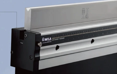
WILA hydraulic lower holders
The illustrated lower-tool holder uses hydraulic clamping with electrically controlled release. Its suitability depends on the selected die interface and machine configuration.
- Hydraulic lower-die retention
- Separate from the standard double-V / T lower clamp
Application-specific
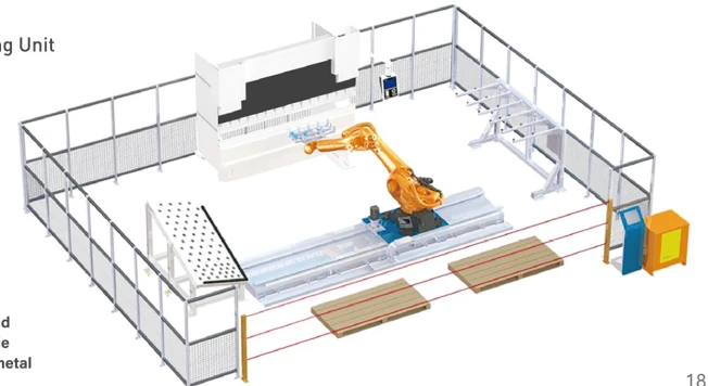
Robotic bending cell
The catalogue shows a flexible bending cell combining the press brake, robot and workpiece-handling areas. The layout is a reference concept, not a fixed package or a documented customer installation.
- Cell layout developed around the workpiece and production sequence
- Robot, handling, guarding and machine interfaces defined together
Continue your configuration.
Use the series pages to compare machine configurations and model parameters, and discuss compatibility before selecting equipment.
Bring us your part requirements.
Discuss the material, geometry and production needs behind your configuration.